6 Essential Parts of a Cylinder Head: Functions & Roles Explained:
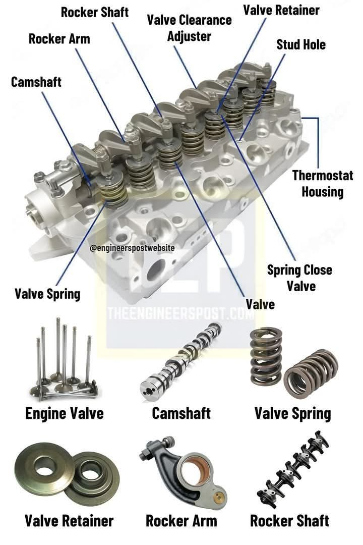
A cylinder head is a crucial component in an internal combustion engine, covering the cylinders and housing vital engine components as the upper part of the engine block. Here’s a breakdown of the key parts:
1. Engine Valves:
These are responsible for controlling the flow of air and exhaust gases into and out of the combustion chamber. There are usually two types: intake valves (allowing air/fuel mixture into the cylinder) and exhaust valves (allowing the exhaust gases to exit).
2. Camshaft:
The camshaft controls the timing and movement of the engine valves. It has lobes that push against the valve lifters or followers, causing the valves to open and close in a precise sequence during the engine cycle. The camshaft is usually driven by the crankshaft via a timing belt or chain.
3. Valve Spring:
This component provides the necessary force to close the engine valves after they have been opened by the camshaft. Valve springs are designed to keep the valves seated tightly against their respective seats to prevent any leakage and ensure proper compression.
4. Valve Retainer:
The valve retainer holds the valve spring in place and ensures the spring stays properly seated. It prevents the spring from coming loose and disrupting the valve’s operation.
5. Rocker Arm:
The rocker arm is part of the valve actuation system. It transfers motion from the camshaft to the engine valve, pushing down on the valve stem to open the valve. The rocker arm is positioned on top of the cylinder head.
6. Rocker Shaft:
The rocker shaft provides a mounting point for the rocker arms. It is typically a long, sturdy bar that supports the rocker arms and allows them to pivot as they open and close the valves.
6 Essential Parts of a Cylinder Head: Functions & Roles Explained:
A cylinder head is a crucial component in an internal combustion engine, covering the cylinders and housing vital engine components as the upper part of the engine block. Here’s a breakdown of the key parts:
1. Engine Valves:
These are responsible for controlling the flow of air and exhaust gases into and out of the combustion chamber. There are usually two types: intake valves (allowing air/fuel mixture into the cylinder) and exhaust valves (allowing the exhaust gases to exit).
2. Camshaft:
The camshaft controls the timing and movement of the engine valves. It has lobes that push against the valve lifters or followers, causing the valves to open and close in a precise sequence during the engine cycle. The camshaft is usually driven by the crankshaft via a timing belt or chain.
3. Valve Spring:
This component provides the necessary force to close the engine valves after they have been opened by the camshaft. Valve springs are designed to keep the valves seated tightly against their respective seats to prevent any leakage and ensure proper compression.
4. Valve Retainer:
The valve retainer holds the valve spring in place and ensures the spring stays properly seated. It prevents the spring from coming loose and disrupting the valve’s operation.
5. Rocker Arm:
The rocker arm is part of the valve actuation system. It transfers motion from the camshaft to the engine valve, pushing down on the valve stem to open the valve. The rocker arm is positioned on top of the cylinder head.
6. Rocker Shaft:
The rocker shaft provides a mounting point for the rocker arms. It is typically a long, sturdy bar that supports the rocker arms and allows them to pivot as they open and close the valves.
0 Comments
0 Shares